PDX Voltage Amplifiers
The PDX voltage amplifiers set a new standard for the bandwidth and power of piezoelectric drives. The exceptional bandwidth with large capacitive loads and the high output current enables a range of new applications not previously possible. The PDX amplifiers are employed in demanding applications such as high-speed physics, video-speed microscopy, precision manufacturing and piezoelectric vibration control.
The PDX amplifiers are available in two output voltage ranges and three peak current ranges. The b variant is designed for general purpose and scanning applications where peak current may last for up to 100ms. The c variant is designed for applications where a large output current is required for a short period of time. The d variant provides up to 10A of current for applications that require fast step changes in voltage.
The PDX amplifiers contain a new technology called Dynamic Current Control. Compared to other amplifiers with fixed current limits, Dynamic Current Control dramatically improves the maximum output current which allows the reproduction of larger amplitude waveforms with higher frequency. In addition to the fast response, the PDX amplifiers are also easy to use and can drive any capacitive load. Other features include: comprehensive overload protection; an external shutdown function; voltage and current monitor outputs; and front-panel bias-voltage adjustment.
- Download Datasheet
- Download User Manual
Enquiry
Obtain a quote
Specifications
| Model | PDX150 | PDX200 | ||||
| Variant | b | c | d | b | c | d |
| Peak Current | 2A | 5A | 10A | 1.5A | 5A | 10A |
| OverloadTime | 100ms | 1ms | 100us | 100ms | 1ms | 100us |
| RMS Current | 1.6A | 1.1A | ||||
| Voltage | -30V to 150V* | -30V to 200V* | ||||
| Gain | 20 V/V | |||||
| Signal Bandwidth | Greater than 80 kHz (1uF Load) | |||||
| Power Bandwidth | 9.5 kHz | 7.2 kHz | ||||
| Offset | From 0V to Full-Range with front panel adjustment | |||||
| Input | Differential, Zin = 22 k | |||||
| Signal Connectors | BNC | |||||
| Output Connector | LEMO and 4mm Jack | |||||
| Load | Stable with unlimited capacitive loads | |||||
| Overload | Thermal, current and voltage overload protection | |||||
| Noise | Ultralow noise, < 320 uV RMS | |||||
| Environment | 0 – 40 C (32-104 F), Non-condensing humidity | |||||
| Enclosure | Rugged desktop enclosure. Rack compatible | |||||
| Dimensions | 212.6 x 304.8 x 132.6 mm (w x d x h) | |||||
| Power Supply | 115V or 230V AC (selectable) | |||||
Power bandwidth
The power bandwidth is the maximum frequency sine-wave that can be reproduced at full voltage. The b variants of the PDX150 and PDX200 are designed to maximize the power bandwidth in general purpose and scanning applications. With a capacitive load, the maximum frequency sine wave is $$f^{max}=\frac{I_{pk}}{V_{p-p} \pi C}$$ where \(I_{pk}\) is the peak current, and \(V_{p-p}\) is the peak-to-peak voltage. A table of the approximate power bandwidths for a range of capacitive loads is shown below.
| Capacitance | PDX150b | PDX200b |
| 100 nF | *9.5 kHz | *7.2 kHz |
| 300 nF | 9.2 kHz | *7.2 kHz |
| 1 uF | 4.2 kHz | 2.3 kHz |
| 3 uF | 1.4 kHz | 790 Hz |
| 10 uF | 424 Hz | 230 Hz |
| 30 uF | 141 Hz | 79 Hz |
| 100 uF | 42 Hz | 23 Hz |
Power Bandwidth versus Load Capacitance
* With very small loads, the power bandwidth is limited by the slew-rate, which is approximately 4.5 V/us. This can be doubled to 8 V/us if necessary.
Also of interest is the maximum amplitude sine-wave that can be delivered to a capacitive load versus frequency. This relationship is plotted below and can be computed for a specific capacitance by using the links above.
Frequency Response
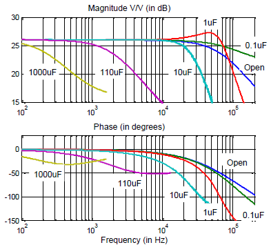
The PDX amplifiers have an extremely wide bandwidth and can tolerate any capacitive load. The frequency response and small-signal bandwidth are described in the following figure and table.
| Capacitance | Bandwidth |
| No Load | 78 kHz |
| 0.1 uF | 200 kHz |
| 1.0 uF | 84 kHz |
| 10 uF | 27 kHz |
| 100 uF | 2.7 kHz |
Bandwidth versus Load Capacitance
Noise Performance
The PDX amplifiers are low noise devices designed to exceed the requirements of positioning and imaging systems with sub-atomic resolution. The following table lists the output noise voltage versus load capacitance.
| Capacitance | Bandwidth | Noise (RMS) |
| No Load | 78 kHz | 300 uV |
| 100 nF | 200 kHz | 320 uV |
| 1 uF | 84 kHz | 312 uV |
| 10 uF | 27 kHz | 280 uV |
| 100 uF | 2.7 kHz | 167 uV |
| 1000 uF | 270 Hz | 192 uV |
RMS Noise versus Load Capacitance
Signal Conditioning
The differential input circuit eliminates ground-loops and noise resulting from the interconnection of different instruments.
Enclosure
The PDX amplifiers are housed in a desktop enclosure that can be bolted together in a side-by-side configuration. Mounting in a standard 19-inch rack is also possible with the addition of rack-mount handles.
Options
The PDX amplifiers can be customized to meet a range of industrial or scientific requirements. Specific options
include:
- 19-inch rack kit for two amplifiers
- 19 inch rack kit for a single amplifier


